![]()
|
新『コロンブスの電磁気学』(第3巻) 縦列接続の登場 |
"Copernican Revolution of Electromagnetism“
BOOKⅢ Introducing tandem connections |
||||||||||||||||||
|
『ファラデー 電気実験(上)
M.Faraday著 監修者:田中豊助 (株)内田老鶴圃』に於いて、ファラデーは次の記述を残しています。
このファラデーの記述にあります「他の針金の中にわずか一瞬しか持続しない電流」を、一般的には“クロストーク”と称していると私は教わりました。
しかし、ファラデーが使いたくても使えなかった現在の電気測定機器を用いて、「コロンブスの卵」的な発想での実験を行えば、「2本の電線間の電流の流れ状態」が、全く異常ではなく、理に適っていることが判明するのです。
即ち、更に実験を続けると、入力線の横に存在する隣接線にも、入力線を流れる電流同様の電流が流れていることが判明するのです。
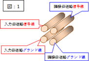
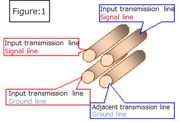
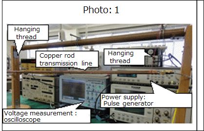
そこで、銅の丸棒を用い、5mmφの1㍍長の銅の丸棒を4本用いて「図:1」並び「写真:1」のような入力伝送路、並びに、隣接伝送路を作成しました。
但し、各伝送路の特性インピーダンス値も50Ωとなるように導体間隔を調整して、各伝送路(各伝送路のZ=50Ω)の末端を50Ω整合終端処理しました。
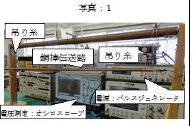
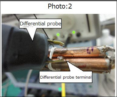
尚、隣接する隣接伝送路の後部(入力信号の進行方向と反対側)を同軸ケーブルで約4cm延長し、その末端を50Ω整合終端処理した状態として、隣接伝送路へ誘起される電流を、差動プローブ(「写真:2」)、オシロスコープを用いて測定致しました
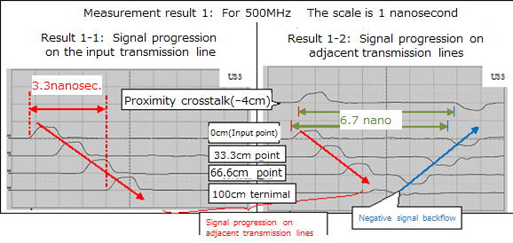
この入力伝送路に、パルスジェネレータから500MHzの矩形波信号を1パルス入力し、その進行状況(電圧変化)を、入力伝送路の各部(0、33.3、66.7、100cmの地点)に於ける電圧変化を測定し「測定結果:1-1」を得ました。
更に、隣接する隣接伝送路の後部を同軸ケーブルで約4cm延長して(-4cmの地点)で得られる近端方向(注)へ向かう電気信号、更に遠端(注)へ向かう電気信号を0、33.3、66.7、100cmの地点で差動プローブを用いて測定し、次の「測定結果:1-2」を得ました。
(注:一般的に、隣接伝送路に於いて、入力伝送路の入力側を近端、入力伝送路の末端側を遠端と称しますので、本著でもその呼称に準じます)
この測定結果に於いて、注目すべき点は、空気中に設置した1㍍長の入力並び隣接両伝送路を、同一形状の電気信号が、空気中の電磁波速度で同時進行していることです。
更には、隣接伝送路では遠端部で、遠端クロストークが符号を逆転して、近端側へマイナス信号として逆流する点です。(往復時間:約6.7ナノ秒=3.3ナノ秒×2)
(隣接伝送路の末端(遠端)では、プラス/マイナス信号が相殺しています)
更に、入力信号の周波数を変化させ同様な測定を行っても、この状況は変わらず“隣接伝送路では遠端部で、遠端に向かう信号波形の正負が逆転して、近端側へマイナス信号として逆流する”現象が次々観測され「ファラデーの誤解」に至る過程が明らかになります。
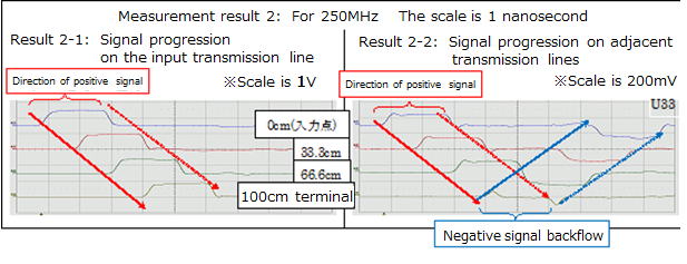
例えば、250MHz(1V/0V)の場合で、測定状況は、勿論、500MHzの場合同様です。
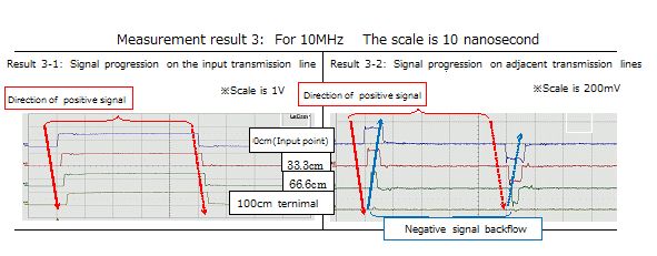
次には、10MHzの場合での測定結果を次に掲げます。
この結果(隣接伝送路での信号の進行)に見る波形形状はファラデーが誤解した「ファラデーの電磁誘導現象」に、少し似てきます。
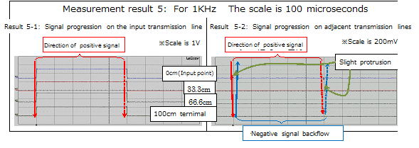
更に、波長の長い1MHzの場合となると、「ファラデーの電磁誘導現象」そのものと見紛うような観測結果が得られます。 更に、次は1KHzの場合です。
このような、全く「ファラデーの電磁誘導現象」そのものと見紛う観測結果が得られますが、その近端で観測される波形を同一時間軸で観測すると、すべて同じ波形なのです。
これらの場合と全く同様な波形変化を、末端がショート状態の入力伝送路単独の場合の入力部での電圧波形変化にも観測するのは当然です。
そして、ここまでの測定結果から、「ファラデーの電磁誘導説」は誤解の産物であることが分かります。
では、何故、隣接線(隣接伝送路)は、入力線(入力伝送路)と同じ電気信号が流れるのでしょうか?
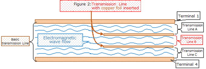
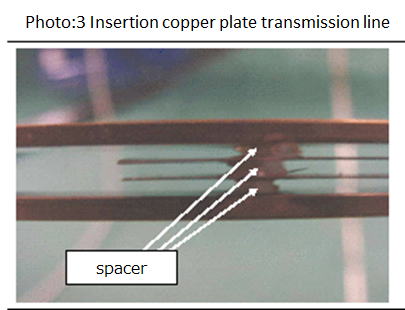
それは、別冊『新『コロンブスの電磁気学』第1巻 新たな電流理論』の「第4章 電流の担い手は電荷でしょうか?」に於いて、次の「図:2」(写真:3)の伝送路系の各伝送路に同形の電気信号が流れる事から、その「図:2」に書き込みましたように”電流の担い手は電荷ではなく、電磁波の流れ、即ち、電磁子集団の流れ”であって、それ等各伝送路は、縦列接続(pile connection)の関係にあるからです。
では、何故「縦列接続(pile connection)」の関係にある伝送路には同形の電気信号が流れるのでしょうか?
この件は是非とも本著を御高覧下さい。
目次
まえがき
第1章 ファラデーの誤解を現在の測定器で解きます
第2章 隣接線に誘起される電流 第3章 隣接伝送路にも入力信号と同形の信号が流れます
補足 隣接伝送路の近端側を延長した場合
第4章 隣接線には入力信号と同形の信号を相殺する信号も流れる
補足:1 「隣接伝送路」の末端状態を変えた場合
補足:2 矩形波以外の入力信号の場合
第5章 一般電線を用いて「ファラデーの誤解」を解きます
補足 特性インピーダンス値が50Ω以外の伝送路の計測(マッチング抵抗)
第6章 縦列接続の登場
第7章 縦列接続の誕生
補足 縦列接合を活用して直流用トランスの開発
第8章 縦列接続の展開
第9章 縦列接続伝送路の合算特性インピーダンス
補足 抵抗の直列接続は、縦列接続と等価
第10章 縦列接続伝送路に流れる電流は同一値
第11章 隣接伝送路へのマイナス反射波の発生に関する考察
補足:1 入力伝送路との関係を疎遠にすると逆符号の電流が逆流する
補足:2 縦列並び並列接続された伝送路の特性インピーダンス値
補足:3 入力並び隣接伝送路の末端状態を変化させた場合
第12章 変位電流も誤解の産物です
第13章 「ファラデーの誤解」に長年気が付かなかった理由
第1節 先進波と後進波に分裂する原因
第2節 先進波と後進波に分裂する原因の検証(1)
第3節 先進波と後進波に分裂する原因の検証(2)
あとがき
使用した主な測定機器類ほか |
Based
on the magnet results I had obtained up to this point, the battery current
through one wire actually produces the same current in the other wires, but
lasts only for a moment. Yes, rather than the current of a Voltaic battery, it
has the property of an electric wave passing by the impact of an ordinary
Leyden jar, so it barely works on a galvanometer, but it magnetizes the steel
needle. I believed that I must be able to do it.
However, if Faraday conducted an experiment with the idea of Copernican Revolution using the current electrical measuring equipment that he could not use even if he wanted to use it, the "current flow state between the two wires" was not abnormal at all. It turns out to be suitable for.
Further experiments reveal that the adjacent line next to the input line also has a current similar to the current flowing through the input line.
Therefore, using copper round bars, I created input transmission lines and adjacent transmission lines as shown in "Figure: 1" and "Photo: 1" using four copper round bars with a length of 5 mmφ and a length of 1 meter.
The conductor spacing was adjusted so that the characteristic impedance value of each transmission line was also 50Ω, and the end of each transmission line (Z = 50Ω of each transmission line) was subjected to 50Ω matched termination processing.
The rear part of the adjacent transmission line (opposite the direction of travel of the input signal) is extended by about 4 cm with a coaxial cable, and the end is subjected to 50Ω matched termination processing, and the current induced in the adjacent transmission line is applied. Measured using a differential probe ("Photo: 2") and an oscilloscope.
One pulse of a 500MHz square wave signal is input from the pulse generator to this input transmission line, and the progress (voltage change) is measured at each part of the input transmission line (points 0, 33.3, 66.7, 100 cm). Was measured and "Measurement result: 1-1" was obtained.
Furthermore, the electric signal toward the near end (Note) obtained by extending the rear part of the adjacent adjacent transmission line by about 4 cm with a coaxial cable (at the point of minus 4 cm), and the electric signal toward the far end (Note) are 0. , 33.3, 66.7, and 100 cm were measured using a differential probe, and the following "measurement result: 1-2" was obtained.
Note: Generally, in the adjacent transmission line, the input side of the input transmission line is called the near end, and the end side of the input transmission line is called the far end
What should be noted in this measurement result is that electric signals of the same shape are simultaneously traveling at the electromagnetic wave velocity in the air on both the 1-meter long input and adjacent transmission lines installed in the air.
Furthermore, at the far end of the adjacent transmission line, the far end crosstalk reverses the sign and flows back to the near end side as a negative signal. (Round trip time: Approximately 6.7 nanoseconds = 3.3 nanoseconds x 2)
At the end (far end) of the adjacent transmission line, the plus / minus signals cancel each other out.
Furthermore, even if the frequency of the input signal is changed and the same measurement is performed, this situation does not change. "In the adjacent transmission line, the positive and negative of the signal waveform toward the far end is reversed at the far end, and a negative signal is sent to the near end. The phenomenon of "backflow" is observed one after another, and the process leading to "misunderstanding of Faraday" becomes clear.
For example, in the case of 250MHz (1V / 0V), the measurement situation is, of course, the same in the case of 500MHz..
Next,
the measurement results for 10MHz are shown below.
The waveform shape seen in this result (the progress of the signal in the adjacent transmission line) is a little similar to Faraday's misunderstanding of "Faraday's electromagnetic induction phenomenon".
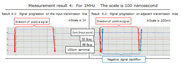
Furthermore, in the case of 1MHz, which has a long wavelength, observation results that can be mistaken for "Faraday's electromagnetic induction phenomenon" itself can be obtained.
Next, the following is the case of 1KHz.
I can get observation results that are completely mistaken for "Faraday's electromagnetic induction phenomenon" itself, but if you observe the waveforms observed at the near end on the same time axis, they are all the same waveform.
It is natural to observe the same waveform change as in these cases in the voltage waveform change at the input section when the input transmission line is short-circuited at the end.
And from the measurement results so far, it can be seen that "Faraday's electromagnetic induction theory" is a product of misunderstanding.
So why does the adjacent line (adjacent transmission line) carry the same electrical signal as the input line (input transmission line)?
As shown in Chapter 4 "Is the bearer of current a charge?" In Volume 1 "New Current Theory", the following "Figure: 2" and "Photo: 3" transmission line system Since electric signals of the same shape flow through each transmission line, as described in "Fig .: 2", "the current bearer is not the electric charge, but the flow of electromagnetic waves, that is, the flow of the electromagnetic group", and each of them This is because the transmission lines are in a pile connection relationship.
So why do the same types of electrical signals flow through transmission lines that are in a "pile connection" relationship?
Please see this book about this matter.
table of contents
Preface
Chapter 1 Solve Faraday's misunderstandings with current measuring instruments
Chapter 2 Current Induced on Adjacent Lines
Chapter 3 A signal of the same shape as the input signal also flows in the adjacent transmission line.
Supplement: When the near end side of the adjacent transmission line is extended
Chapter 4 A signal that cancels a signal of the same shape as the input signal also flows on the adjacent line.
Supplement: 1 When the terminal state of the "adjacent transmission line" is changed
Supplement: 2 For input signals other than square waves
Chapter 5 Solving "Faraday's Misunderstanding" Using General Electric Wires
Supplement: Measurement of transmission lines with characteristic impedance values other than 50Ω (matching resistance)
Chapter 6 Appearance of column connection
Chapter 7 Birth of Column Connection
Supplement Development of DC transformer utilizing column joining
Chapter 8 Deploying Column Connections
Chapter 9 Combined Characteristic Impedance of Column-Connected Transmission Lines
Supplement: Series connection of resistors is equivalent to column connection
Chapter 10 The currents flowing in the column connection transmission line have the same value.
Chapter 11 Consideration on the generation of negative reflected waves on adjacent transmission lines
Supplement: 1 If the relationship with the input transmission line is estranged, a current with the opposite sign will flow backward.
Supplement: 2 Characteristic impedance value of transmission lines connected in parallel in parallel
Supplement: 3 When the terminal state of the input line and adjacent transmission line is changed
Chapter 12 Displacement current is also a product of misunderstanding
Chapter 13 Why people haven't noticed "Faraday's misunderstanding" for many years
Section 1 Cause of splitting into advanced wave and backward wave
Section 2 Verification of the cause of splitting into advanced and backward waves (1)
Section 3 Verification of the cause of splitting into advanced and backward waves (2)
Afterword
Main measuring instruments used, etc.
|